Velleman K8000 - DAC High Power Amplifier - Polarity Reverser
The polarity reversing in this circuit is built with 4 FETs in a so called "H-Bridge": only 2 FETs are conducting at the same time. This will create a path for the current to flow: from left up to right down, or from right up to left down.
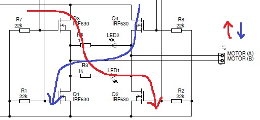
The FETs I have chosen for this bridge are power FETs. They can handle up to 9 Ampères and have a Rds (on) resistance of only 0.2 Ohm. They are are electronic switches. They are not perfect as they always have an internal resistance. This resistance causes a voltage to exist over the drain-source channel. This voltage increases as the current through the FET increases.
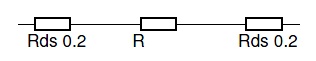
In the image below you can find an equivalent schematics for the current reverser. There is R (the load to control) and two other resistors: 2 other resistors: they represent the Rds resistance of the FETs, which are typically 0.2 Ohm.
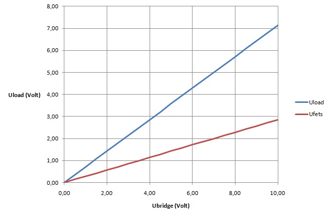
The following graph illustrates how these extra resistors are influencing the available output voltage. I simulated the graph with an output load of 1 Ohm: a voltage of 10 VDC at the input of the FET bridge should cause a current of 10 A.
The X-axis shows a voltage input variation of 0 to 10 VDC. When using perfect switches the output (Uload) should also vary between 0 and 10 VDC. This clearly is not the case when using FETs! The voltage over the FETs will go as high as 3 VDC (this means: 1.5 VDC per FET).
![]()
![]()
Copyright ©1998-2022 Vanderhaegen Bart - last modified: August 24, 2013
