ELECTRONICS - [Morse Code Typewriter] - [page 2/3]
The image below contains the complete schematic diagram for the morse coder device. As you can see the hardware part is very easy to understand.
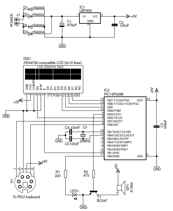
An AC/DC voltage is applied to the connector 'POWER'. This voltage is rectified and flattened by the diodes and the capacitor C1. The voltage regulator LM7805 will turn the voltage into a nice stable 5 VDC voltage.
The circuit is build around the PIC 16F628A. This PIC is running on a 20 MHz crystal. We need this high speed because our controller needs to be fast enough to decode the keyboard signals.
The PS/2 keyboard is connected to the PIC's ports RB0 (CLOCK) and RB1 (DATA). Our keyboard also needs some power: the PS/2 connector is also connected to the GND and +5V lines.
The LCD module requires a little bit more wires: We will run it in 4-bit mode which means we only need the data lines D4 to D7. We also need to control the E-signal (Enable, pin #6) and the RS-signal (pin #4).
The PIC also controls a LED on output RA0 and a speaker on output RB3. This port will deliver a PWM (Pulse Width Modulation) controlled signal. I used a small BC547 amplifying transistor because we can't connect our speaker directly to the PIC's output (it can't deliver enough power).
Information
I have built a very basic amplifier for the morse code speaker. It is no real audio amplifier. You should never apply a flat DC signal at the input of the amplifier. This wil literally cook the loudspeaker!
I used the PIC's build-in PWM generator to generate the audio signal. The PWM output frequence is approximately 1 kHz with a duty-cycle of 50%. This frequence is about the minimal PWM frequence the PIC can output.
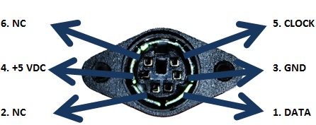
The image below shows you the connections of a PS/2 connector. Only 4 wires are actually in use: +5V, GND, CLOCK and DATA. It is important that you don't switch the polarity of the power supply! This can kill your keyboard as some keyboards aren't protected against a reversed polarity.
![]()
![]()
Copyright ©1998-2022 Vanderhaegen Bart - last modified: August 24, 2013
