VELLEMAN K8055 - [Voltage Recorder]
The Velleman K8055 card comes with two A/D channels that can measure voltages between 0 and 5 VDC. The A/D convertor will convert these into two eight-bit numeric values: a number between 0 and 255. The number 0 corresponds with 0 V, while 255 corresponds with 5 V.
This means the A/D convertor can measure in steps of 5V/255=19.6 mV. You would need a more accurate A/D convertor (more bits) to increase this accuracy.
It is important to realize the K8055 can only measure voltages between 0 and 5 VDC. Low input voltages should be amplified while high voltages must be reduced.
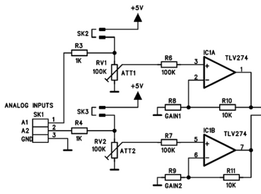
The image below shows a section of the K8055 circuit: You can see the components that are used to amplify or attenuate the DC signals, coming from connector SK1. There is a separate circuit for each input channel. This page will only explain the upper circuit (channel 1).
I performed some tests on the K8055 board: I applied an input voltage between 0 and 5 VDC and found the converted 8-bit A/D value is always lower than the expected value. These measurements were done on a unmodified K8055 board. The table below shows my results. You can clearly see a difference between the actual and theoretical A/D value.
| Uin (V) | AD (Theor.) | AD (Actual) |
| 0.000 | 0 | 0 |
| 0.500 | 26 | 24 |
| 1.000 | 51 | 50 |
| 1.500 | 77 | 74 |
| 2.000 | 102 | 99 |
| 2.50 | 128 | 124 |
| 3.00 | 153 | 149 |
| 3.50 | 179 | 174 |
| 4.00 | 204 | 199 |
| 4.50 | 230 | 223 |
| 5.00 | 255 | 248 |
The table shows there is a measuring error of 255-248=7 A/D steps. This corresponds with a voltage of 7 * 19.6 mV = 137 mV. For labo measurements this is quite a lot. I found there are two major reasons for this measuring error:
The resistor R3 is causing a small voltage drop. This drop is about 50 mV when you apply a 5 VDC voltage at an analog input. A small current flows through resistor R3 and RV1: I = U/(R3+RV1). UR3 can then be calculated with: UR3=I*R3.
The K8055's PIC16C745 microcontroller doesn't convert the analog signals right. A voltage of 5 VDC should be converted to an analog value of 255. This is not the case! I performed some tests and concluded you need to apply 5.12 VDC before the A/D convertor outputs a value of 255.
The PIC16C745's A/D convertor uses the 'successive approximation' conversion method. In order to function it needs a reference voltage. There are two possibilities for this voltage: it can come from an external source, or it can be taken from the PIC's supply voltage: In case of the K8055 the PIC's supply voltage is used. This supply voltage is coming directly from the computer's USB port. Unfortunately the voltage is not exactly 5 VDC. On my computer I measured a voltage of 5.12 VDC. So in short: the reference voltage of the A/D convertor is 120mV/2.4% too high.
You can increase the K8055's A/D convertor if necessary. First of all you could bypass the resistor R3 by a wire. The resistor has no big importance. I think Velleman just put it there as a form of protection. You can increase the accuracy of the A/D channel with 50 mV by bypassing this resistor. Warning: do NOT insert jumper SK2 when the resistor R3 is bypassed.
In the previous topic you could read the PIC's reference voltage is actually 120mV/2.4% too high (The exact voltage might depend on the used computer system). I chose not to tamper with the PIC's supply, but I came up with another solution: I changed the gain of the opamp IC1A so it amplifies the analog input with 2.4%. Doing so an input voltage of 5 VDC will be amplified to 5.12 V, and be converted correctly to the number '255'.
This amplification can be done by installing a resistor for R8 (GAIN). The gain of the opamp is determined by the formula: GAIN = 1 + R10/R8. R10 is the fixed resistor of 10 kΩ. The value of R8 depends on the desired gain. I chose a resistor of 330 kΩ for R10. This value will give you a gain of 3 %. Actually this gain is a little too high but you can compensate it by adjusting the trimmer RV1.
You can actually calibrate the K8055 by changing the value of the trimmer RV1. You should take the following steps:
After this 'calibration' your K8055 card will give pretty accurate readings. The table below shows the results of some test measurements, after my K8055 was modified and 'calibrated'. I varied the input voltage between 0 and 5 VDC in steps of 0.5 V. I measured the results with an accurate multimeter (DVM), and compared them against the readings from my logger software.
| DVM (V) | K8055 (V) |
| 0.000 | 0.000 |
| 0.500 | 0.490 |
| 1.000 | 1.000 |
| 1.500 | 1.510 |
| 2.000 | 2.000 |
| 2.50 | 2.510 |
| 3.00 | 3.020 |
| 3.50 | 3.529 |
| 4.00 | 4.020 |
| 4.50 | 4.529 |
| 5.00 | 5.000 |
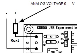
The K8055's A/D convertor can only measure voltages between 0 and 5 VDC. You can measure higher input voltages but then you have to add a resistor between your DC voltage and the input of the K8055:
You can use the following formula to calculate the needed external resistor. See a PDF that explains how I got this formula.
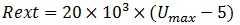
You only need to fill in the maximum voltage you want to measure. The resulting resistance is the minimal value you have to use. You need to pick a higher value if you don't have the exact value.
You should be aware the measuring resolution of the A/D conversion changes when you work with higher voltages. Let's assume you measure a DC signal of 10 V: This 10 V now corresponds with a converted A/D value of 255 and a single A/D step now corresponds with 10 V/255=39 mV.
Conclusion: The accuracy of the A/D conversion decreases when you want to measure higher input voltages.
Copyright ©1998-2026 Vanderhaegen Bart - last modified: August 24, 2013
