ELECTRONICS - [alarm system] - [page 3/8]
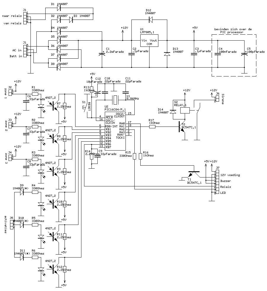
You can view the complete diagram. It contains all parts that are described on this page.
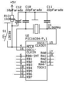
The core of the alarm system is the PIC 16F84 microcontroller. This chip is set to run at a frequency of 8.86 MHz. It has a reset switch,which can be used to reset the controller in case of a failure. It operates at a voltage of 5 V. The Ra a & Rb ports are used for all I/O (sensors, siren, code lock, code lock LED, code lock buzzer, zone1 & zone2 & zone3 activation).
The description of the software inside the PIC is placed on a further page.
The alarm system requires a stable power supply of 5VDC. This is done by a 7805 regulator which is mounted on a heat sink. The capacitors and diodes around it are making sure the 7805 is working correctly.
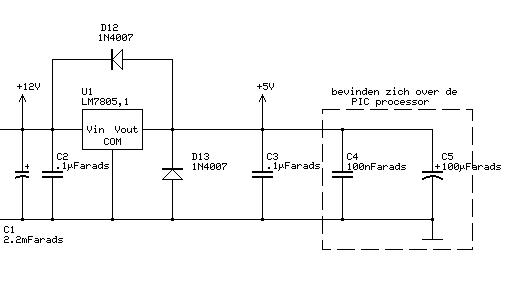
The transformer gives an AC output signal of 12V AC (Alternating Current). This signal must be converted to a DC (Direct current) signal: This is done using a bridge rectifier, consisting of the diodes D5 to D8. The AC input is applied to pin 5 & 6 of connector J1.
The backup battery is applied to pin 7 & 8 of connector J1: If AC power fails the diode D4 will start conducting. Doing so the backup battery can power the system.

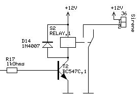
The siren is switched by the relay S2. For this the microcontroller has to set a logical "1" to the input of resistor R17 to make the transistor conducting. Then the relay will close and the Kojak is activated.
All wires for the code lock are connected to J7:
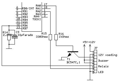
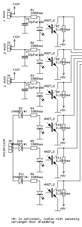
Connectors J2,J3,J4 are used for the sensor inputs. When a complete zone is closed correctly pin #1 & #2 of these connectors are connected: sensors uses a NC contact. If someone cuts a wire, the alarm goes off.
Each input has a capacitor to prevent noice. The information is passed to the PIC through an optocoupler. This was done to protect the microcontroller from sabotage through the sensors. A second reason I used optocouplers was to overcome the voltage levels: the sensors are powered with 12 VDC while the PIC operates at 5 VDC.
The connector J5 is used to connect the zone activation switches. To activate a zone you must connect +12 VDC to its corresponding connection..
![]()
![]()
Copyright ©1998-2022 Vanderhaegen Bart - last modified: February 05, 2017
