VELLEMAN K8055 - [Current Loop Recorder]
Many industrial systems are using current signals to monitor certain devices (like pressure sensors, gas detectors, temperature sensors, ...). The signal is transported over 2 wires. The advantage of working with currents is a current always remains the same, no matter what the length of a wire is.
Most sensors can output a current signal between 4 and 20 mA. The normal output of the sensor is between 4 and 20 mA. A signal lower than 4 mA typically indicates an error.
I have created a 4 - 20 mA datalogger which is build around the Velleman K8055 USB card. This recorder allows you to log a 4 - 20 mA signal coming from a sensor. The software allows you to set the measuring range and unit so it can be used with any kind of transmitting sensor.
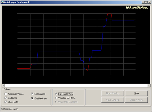
The image below shows a screenshot of the recorder: a graph shows the measured value over time. A red line appears when the measuring signal became invalid: under 4 mA or over 20 mA.
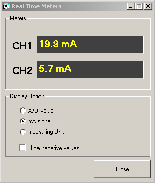
The datalogger also has a window to view the real-time values. You can set the display to either the A/D value, the corresponding mA signal or the true calculated value from the sensor.
My implementation of this 4-20 mA datalogger is very basic. It won't be compatible with all equipment that uses current-loops. It cannot power the 4-20 mA sensor: this voltage has to come from an external 24 VDC source. This is the basic idea:
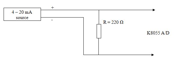
The current source sends it current through the resistor R. This current will cause an electrical Voltage to be over the resistor, which is defined by Ohm's Law: U = I * R. This is the voltage that will be measured by the A/D converter on the K8055.
The K8055 can only handle input voltages between 0 and 5 VDC. This means we have to choose our resistance R careful: I have chosen for a resistance of 220 Ohm. Let's now simulate what the voltages at the input of the A/D converter would be when the current varies between 4 and 20 mA:
Conclusion: in normal circumstances the Voltage at the AD port will vary between 0.88 and 4.4 VDC (3.52V).
The problem with the K8055 card is it only provides an 8 bit A/D converter. This means it will translate the analog signal into a digital signal with just 256 possible values: it will measure in steps of 19.5 mV. Consider a second fact: the current should never drop lower than 4 mA (0.88 V). This means under normal circumstances the input of the A/D converter will only vary between 0.88 and 4.4 VDC. Between these two voltages there are only 176 different levels the A/D converter can measure.
Example: we connect a temperature sensor with a total range of 0 to 100 °C to the K8055. Let's say the sensor is extremely accurate and it has an accuracy of 0.0001°. The effective accuracy would be only 0.56°C!
A second consideration: in case of a hardware error - for example when the resistor R gets disconnected - the current source will be sending all of the electrical current through the A/D converter. This will cause a high voltage to be at the input of the A/D converter. Chances are great the PIC processor of the K8055 will get broken.
I have decided to stop working on this project. You can download my source code as it is at this moment. The software is written in Visual Basic 5.0. You need the DLL from Velleman to get the project working.
Copyright ©1998-2022 Vanderhaegen Bart - last modified: August 24, 2013
