ELECTRONICS - [RS-232 Interface] - [page 1/4]
For over 10 years I've been working with computer interface cards like the Velleman K8000 or the Velleman K8055. Now I took the time to design my own interface system. My very first interface is an interface with only digital outputs. I wanted to build a very flexible interface, you can use between 8 and 120 digital output channels.
I have chosen to use the serial RS-232 protocol for the communication. The protocol is easy to use and can be used over large distance. The downside is this protocol requires a serial DB-9 port. Many modern computers no longer have this port. This is no big problem as there are many cheap USB to RS-232 converters available.
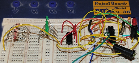
My first version of the circuit is only a breadboard version (prototype). The image below shows the actual setup. This circuit has only 8 digital outputs to control green LEDs. The circuit is powered by a labo power supply, it is not shown on the image. The RS-232 communication part is not shown either, I used a separate PCB for this (RS-232 to TTL converter).
I designed my interface around the PIC 16F628A microcontroller. This controller can run at 20 MHz and has a hardware USART. This allows us to run the commands from the computer as fast as possible.
With the current firmware it is possible to control up to 120 digital outputs. The outputs provide a TTL-voltage level: 0 V or 5 V. The shift register's outputs are powerful enough to drive LEDs directly. You will need some additional hardware to drive larger loads (transistor/FET/optocoupler). It's best to check the datasheet of your version of the shift register. It is possible the manufacturer specified a maximum total current your shift register can handle. You should not exceed this value.
My interface board is very flexible: It uses shift registers to control the digital outputs. You need to place a single shift register for each group of 8 outputs. The nice thing about my system is that it you can customize it very easily: you can choose to use only one shift register (8 outputs) or you can choose to use 15 shift registers (120 outputs). No firmware modifications need to be done! The transmitter (computer) will tell the interface how much shift registers are used.
I have written my own communication protocol to communicate between PC and microcontroller. The protocol uses a checksum to check if there were no communication errors.
Warning:
This computer interface does NOT provide an optical isolation between the computer and the digital outputs. If something real bad happens, your computer could get damaged.
I advise to use this circuit to control LEDs only. You can control other kinds of devices, but then you should add an electrical isolation between this interface and your own circuits. You could do this by adding relays or optocouplers.
This is a larger project so I have split it into different sections:
![]()
![]()
Copyright ©1998-2022 Vanderhaegen Bart - last modified: August 24, 2013
