ELECTRONICS - [PC Standby Detector]
Many computer systems have a blinking power LED when they are in standby mode. This can be annoying and there is often no way to disable the flashing standby LED. So you can either disable it completely by disconnecting the power LED, or you could add a switch between the motherboard and the LED.
I have made a third solution: a little electronic circuit that is placed between the motherboard and the LED. The circuit detects whether the motherboard is sending a constant (computer running) or a pulsing (standby) voltage to the LED. The output of the circuit will control the LED of the computer.
This project is a rather complicated solution: the electronic circuit will require some external power. I myself don't use this solution. I created this project with the purpose to test my Velleman K8055 based voltage datalogger.
If you are really interested in turning off the annoying flashing standby light, here is my solution: unplug the power LED connector from your motherboard, and connect it to a molex connector from a hard disk instead. There is a 12 V voltage between the YELLOW and the BLACK wires. On many computer systems this voltage is cut off when the computer is in standby mode, so the LED won't light up then.
The circuit has to determine if the an input from the motherboard is constant or pulsing. This can be done by applying the signal to a capacitor. The values of this capacitor and its surrounding resistors should be chosen with care. When they correctly dimensioned there are two possibilities:
This capacitor's voltage has to be compared with a reference voltage, that is set by a variable resistor (trimmer). You should set a reference voltage that is only reached when the motherboard gives a constant voltage.
The comparing itself is done with an Operational Amplifier. It has a binary output: "low" or "high". The Opamp will only give a "high" output when the capacitor's voltage exceeds the reference voltage. The output of the Opamp will control the LED inside the PC housing.
In short: This circuit should be placed between your motherboard and the PC LED. The signal from the motherboard must be applied to the input of this circuit. The output of the Opamp must be connected to the power LED of the computer case. The opamp will make the LED light up only when the input voltage from the motherboard is constant.
Here you can find the schematic diagram for the pulse detector. The circuit below is dimensioned for a pulse that is 2 seconds "ON" and then 2 seconds "OFF". A pulse with another frequency requires other component values.
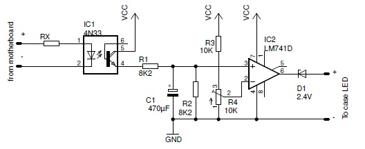
The circuit should be powered by a stabilized 12 VDC supply (Vcc=12 V). You could take this voltage directly from the supply unit in your PC but you should be aware many of its output voltages are cut off when the computer is in sleep/standby mode.
The input signal from the computer is applied to an 4N33 optocoupler. This creates a galvanic separation between the motherboard and your circuit, to protect your motherboard from any damage through this circuit.
The value of the resistor Rx depends on the output voltage of your motherboard. According to the 4N33's datasheet the forward voltage for its internal emitting diode is typically 1.2 V/10 mA. With this information we now can write a formula to calculate the necessary value for Rx:

The optocoupler contains an internal photo transistor, which catches the infrared light from the emitting diode. The collector-emittor junction will conduct only when it emits: when the motherboard gives a voltage. There are two possibilities:
The voltage from the capacitor is brought to the pin #3 of the Opamp (non inverting input). This voltage will now be compared with a reference voltage, set by the trimmer R4. The reference voltage can be anything between 0 and Vcc/2. The Opamp can have two output conditions, depending on the signal from the motherboard:
The output of the Opamp is about Vcc-2 V when it is "high", and it is 2 V when it is "low": it is never really 0 V. This is because the 741 is supposed to be used with a symmetrical power supply (e.g. +12/-12 V). You can overcome this by placing a small 2.1 V zenerdiode in series with the output LED, or by using a better Opamp (The 741 is the only type I currently have).
The resistors R1,R2 and the capacitor C1 need to be dimensioned properly. Otherwise the detector won't work. There are 2 considerations:
The RC time constant can be calculated by multiplying the resistor R with the capacitor C, or time constant = R * C. We can now come use two possible formulas:
My circuit was originally designed for a pulsing signal with a period of 4 seconds. I chose a capacitor of 470 µF and calculated the required resistors: R=period/C=4s/470µF=8695 Ohm = 8.6 k.
Lets assume you want to convert the circuit to detect pulses with a frequency of 50 Hz. A capacitance of 470 µF is way too high, so we take a lower one: 4.7 µF. Now we can calculate the required resistance: R=20ms/4.7µF=4255 Ohm. So you need a value of 4.2k for resistors R1 and R2, and a value of 4.7 µF for capacitor C1.
I did some measurements to show what is happening when the circuit is working. The blue graph shows the input voltage from the motherboard, the red graph shows the voltage over the capacitor C1. (The measurements were done with the aid of my K8055 voltage data recorder). The following graph shows a full testing cycle. It starts when the computer was in the 'OFF' position, and has 5 testing phases:
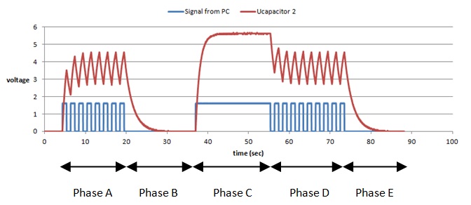
The graph clearly shows the capacitor's voltage is higher when the computer is in the ON-state: 5.6 V versus 4.7 V when the computer is in standby. This means you should set the reference trimmer to a voltage between 4.7 and 5.6 V.
The circuit works for sure, but as I mentioned before: it is a complex solution for a rather simple problem.
The circuit can deal with higher frequencies, like a 50 Hz signal. You could use it to detect whether a user applies AC/DC at the input of a circuit. You can also invert the function of the comparator, by toggling the inverting/ non-inverting inputs.
Be careful when you apply AC signals at the input of the optocoupler: it only allows a limited reverse voltage of 3 V. You should avoid negative voltages by adding a protection diode.
Copyright ©1998-2022 Vanderhaegen Bart - last modified: August 24, 2013
