Velleman K8055 - [K8055 Hardware Tutorial]
The Velleman K8055 has five digital outputs who know only two different states: ON or OFF (1 or 0). The current state is indicated by a LED on the K8055 board. There is a LED for each channel.
Using the digital outputs can be confusing. First of all you should realize these outputs do not output a voltage, they act like switches. You first need to apply an external power source to the K8055. Velleman is giving this schematic diagram to create the required connections:
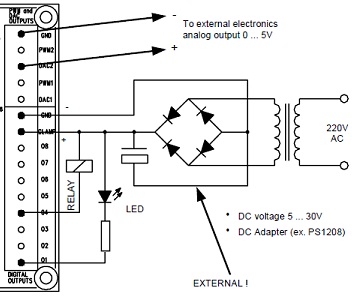
You should connect an external power source with a voltage between 5 and 30 VDC.
The K8055 has some internal electronic switches between each digital output and the GND. Once a certain output is activated the switch is closed. Now an electrical current can flow through the LOAD: the LOAD is now activated.
Velleman specifies the electronic switch inside the K8055 can control currents up to 100 mA. This is not completely accurate: the K8055 uses the UNL2803 driver to switch the currents. Its data sheet specifies its maximal current is 500 mA. BUT: the is the total current the chip can handle. So: one channel can switch 500 mA. Two channels can switch 250 mA, ...
The maximal currents are quite low. You will need to add some external circuitry to switch higher currents. The easiest way is a relay. Other ways are a transistor, a FET, a triac, ...
Almost everyone knows how to connect the relay so what about a ... FET? They have the advantage to switch currents on/off very fast, much faster than a relay. You could use a FET (Field Effect Transistor) to control high currents. I made a sample with the IRF630. This is a N-channel power MOSFET that can control currents up to 9 A. Their internal Rds value is low which means the FET doesn't dissipate too many heat.
The image below shows you a possible circuit you can use to control a FET with the Velleman K8055. This FET will switch a certain 12 V controlled LOAD, let's say a halogen lamp. This lamp is placed between the +V and the drain- connection of the FET.
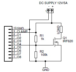
Unlike the transistor, a FET is voltage-controlled. All you need to do is to apply a (sufficient) voltage between the gate and the source. I placed a resistor R2 between the gate and the source to make sure the gate is never floating: this would be bad for our (expensive) FET. A FET is very sensitive to electro static discharges: you might break the FET just by touching the gate.
During operation there are two possibilities:
You will probably notice the operation of the switch is inverted: the load is activated if the output O4 is inactive and vice versa. Maybe you don't like this. You can overcome this by some additional components to the circuit. I didn't do this because I 've tried to keep the example as easy as possible.
The following sample program controls a basic traffic light: O1 represents the green, O2 the yellow and O3 the red light. The code is written for Visual Basic 2010. you need to create a new project with an empty form: Form1. You don't need to place any components on the form but you do need to add my K8055 class to your project.
    Public Class Form1
      Dim myK8055 As New K8055()
      Dim WithEvents timer As New Windows.Forms.Timer

      Private Sub Form1_Load(ByVal sender As System.Object, ByVal e As System.EventArgs) Handles MyBase.Load
        myK8055.connect(SK5:=False, SK6:=False)
        With timer
          .Enabled = True
          .Interval = 1
      	End With
    	End Sub


      Private Sub timer_Tick(ByVal sender As Object, ByVal e As System.EventArgs) Handles timer.Tick
        Static currentLevel As Integer = -1
        currentLevel = (currentLevel + 1) Mod 3
        myK8055.clearAllDigtalOutputs()

        Select Case currentLevel
        Case 0
          myK8055.setDigitalOutput(1)
          timer.Interval = 10000
        Case 1
          myK8055.setDigitalOutput(2)
          timer.Interval = 2000
        Case 2
          myK8055.setDigitalOutput(3)
          timer.Interval = 10000
        End Select
      End Sub
    End Class
The program creates an timer object: It will fire a timer.Tick event at certain intervals. The used interval always depend on the current output state (green/yellow/red): the duration for the green/red light is 10 seconds, while the duration for the yellow is only 2 seconds.
The output state is kept by a static variable (currentLevel). These kind of variables are keeping there value, even if you leave the procedure in which they are created. Each time the timer.Tick event is launched, the value of the currentLevel variable is increased with 1. Then there is a modulus operation performed on the result, to make sure the result can only be 0,1 or 2 (green,yellow,red).
I used a SELECT CASE to determine the current output state. For each state I defined what the outputs should be, and when the next timer.Tick event should occur (the given times are expressed in milliseconds).
![]()
![]()
Copyright ©1998-2026 Vanderhaegen Bart - last modified: August 24, 2013
